Non-structural elements are not designed to withstand seismic forces beyond their mass. These elements can be categorized into three groups: architectural features like cladding panels and partition walls; mechanical and electrical components such as elevators and plumbing; and building contents, encompassing items like bookcases. Two compelling reasons to seriously consider the seismic performance of these elements are the potential danger they pose to people both inside and near a building and the significant economic investment in buildings and businesses housed within them.
Non-structural damage in earthquakes results from ground acceleration and inter-story drift. As a building resonates, higher floors experience increased acceleration amplification, inducing inertia forces in non-structural elements (Figure below (left)). This leads to sliding, overturning, and detachment, causing additional damage. Two preventive strategies involve ensuring sufficient strength in non-structural elements and physically restraining them by attaching them to structural members. Inter-story drift, where floors sway horizontally, can harm elements connecting both floors, but careful separation can mitigate this damage (Figure below (right)).
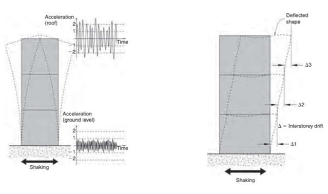
Figure 10.1 Shaking at base amplified as it travels upward & Figure 10.2 Intersorey drift from EQ shaking. From SDA Pg. 159.
Infill Walls
Infill walls, typically part of a building’s cladding system, are placed between structural elements like columns and beams. While they are not primarily designed to resist forces, their stiffness inadvertently makes them react to seismic forces, often leading to structural damage. In certain conditions, like in low-rise buildings without other seismic systems, properly placed and unmodified infill walls can be effective against seismic forces. However, alterations to these walls can negatively impact a building’s seismic performance. Unreinforced masonry or concrete block infill walls, in particular, can cause significant issues. Their stiffness can lead to concentrated forces at frame junctions, potentially causing shear failure and collapse. Additionally, asymmetrically placed infill walls can alter the building’s Center of Rigidity, leading to torsional effects and uneven stress distribution. (Figure below (a))
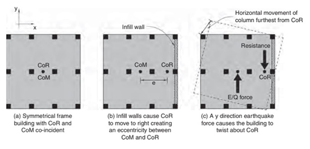
Figure 10.8 Infill walls that are unevenly distributed can induce torsional stress in a building, leading to damage in columns located far from the center of resistance. From SDA Pg. 162.
To address these issues, three main solutions are suggested. One is transforming infill walls into confined masonry, fully integrated with the structural frame, which is effective but architecturally restrictive. Another is using a very stiff primary structure like reinforced concrete shear walls, which limits inter-story drifts and allows for the presence of masonry infills. The third, and increasingly common, solution is to separate infill walls from frames (Figure above (b)). This approach, widely adopted in seismically active regions, involves creating gaps to allow the frame to move without being impeded by the wall. However, separation introduces challenges in maintaining architectural integrity, including acoustic control, weather tightness, and fire protection.
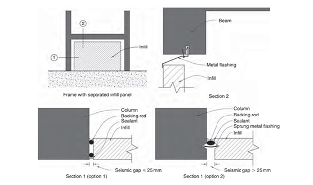
Figure 10.10 Common architectural designs for separation gaps between a frame and infill wall. From SDA Pg. 164.
Separated infill walls, while free from in-plane movement, become vulnerable to out-of-plane forces. Solutions include cantilevering from the base or spanning vertically between floors. For unreinforced masonry, small reinforced concrete columns within the wall might be used for stabilization. These solutions aim to balance the need to resist out-of-plane forces while allowing for inter-story drifts. In some designs, infill walls are offset from primary columns, functioning as partition walls or exterior cladding to alleviate separation difficulties.
Staircase
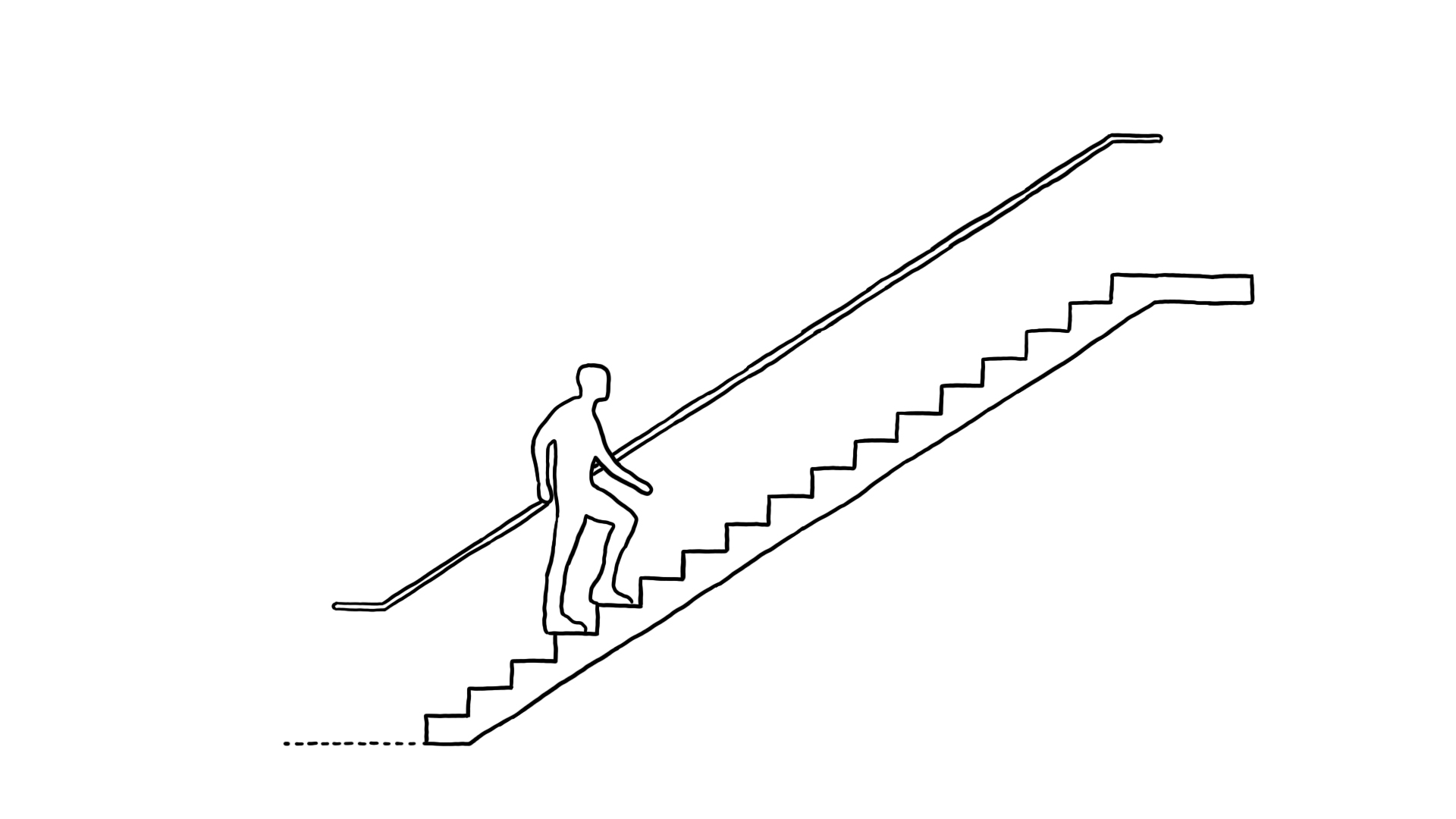
When staircases are firmly integrated with a building’s structure, they can act as structural members due to their inclined shape, potentially functioning like diagonal braces (Figure below). These braces, being part of a triangulated framework, are highly resistant to horizontal forces compared to moment frames. This can lead to staircases experiencing unexpectedly high levels of force during seismic events. If stairs sustain severe damage, it may impede the safe evacuation of building occupants after an earthquake. Additionally, asymmetrically positioned staircases can cause torsional stress in the building. For example, a staircase placed near the right-hand edge of a floor plan can shift the Center of Rigidity to the right, creating torsion.
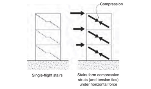
Figure 10.19 Bracing action of stairs connected to structure. From SDA Pg. 168.
To mitigate damage to both the staircase and the building’s structure, a recommended solution is to install sliding joints on each floor (Figure below). These joints allow inter-story drift between floors in any direction without causing restraint. As a result, when drifts occur, the stairs can slide over the lower floors, attracting minimal seismic force due to their relatively lightweight. Creating sliding joints is straightforward and involves breaking the bond between the stair and its base support, allowing the stair to slide if the upper floor drifts more than the lower one. The stair can be either pin-jointed or rigidly fixed into the floor above. All inertial forces of the staircase, including those perpendicular to its direction, must be transferred back to the main structure. In some cases, more sophisticated materials like Teflon strips on stainless steel plates are used to create low-friction sliding joints, although such complexity might be unnecessary. Additionally, the separation of switch-back or dog-leg stairs with a half-story-height landing involves more complex detailing.
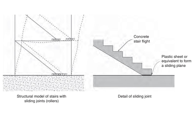
Figure 10.21 Single-flight stair separation. From SDA Pg. 169.
Cladding
Cladding is the term used for the non-structural outer layer or facade of a building. Claddings vary widely in material, reflecting the diversity of architectural styles and environments. Unreinforced masonry, sometimes plastered, is a universal cladding material. In more affluent countries, advanced cladding options like glass fibre reinforced cement (GFRC) panels, titanium sheets, and fully-glazed curtain walls are prevalent. This discussion will focus on three primary categories of cladding: masonry, panels, and a variety of other materials.
Masonry
Seismic considerations for masonry cladding, although similar to infill walls, are somewhat simpler. While external masonry walls are not technically infill walls, they exhibit similar seismic vulnerabilities. To mitigate these risks, especially in buildings without stiff shear walls, it is recommended to separate these non-structural masonry walls from the main structure. This separation helps prevent both direct damage, such as in-plane cracking, and indirect damage to the primary structure. Brick veneer is a common cladding choice, but it has been shown to be vulnerable to earthquakes. Veneers, which are self-supporting, must be anchored back to the internal structure, usually via reinforced masonry walls or vertical wood or steel studs. These structures transfer inertia forces from the veneer to the building’s floors and ceilings, providing out-of-plane resistance.
For optimal seismic performance, veneers should be firmly tied to the structure to handle both tension and compression forces, and veneer tie spacing should meet code requirements. Additionally, veneer ties should be flexible to allow the primary structure to deflect horizontally without damaging the stiffer veneer. Nevertheless, flexibility differences between the veneer and the structural framework often lead to damage concentration at corner joints. While wide vertical separation gaps could prevent this damage, they are usually deemed impractical, resulting in inevitable damage in these areas (Figure below). In high-rise buildings, specific measures like steel angles support the veneer’s weight, and additional precautions such as reduced tie-spacing and horizontal reinforcements may be necessary to counteract increased seismic forces.
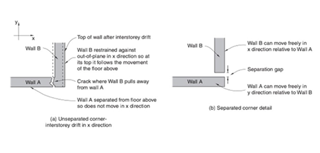
Figure 11.3 Intersection drift can damage the corners where walls connect to the structure above unless (a) unless a vertical separation gap, yet to be treated architecturally, is provided (b). From SDA Pg. 169.
Panels
Cladding panels, often made of concrete and posing a hazard if removed, necessitate careful design to avoid damaging the primary structure during seismic events. To mitigate risks, designers typically separate these panels from the structure and each other, unless the panels are integrally connected as shear walls. This approach is similar to the flexible yet attached nature of snake or fish scales, allowing cladding panels to accommodate the primary frame’s movements without resistance.
Two common methods for connecting and separating story-height panels include hanging a panel from the top with a gap below or supporting it at the base with a gap above. These gaps accommodate inter-story drift, allowing panels to remain vertical and move with the floor providing gravity support. All panel connections are designed to resist out-of-plane forces, with some allowing horizontal seismic movement and others handling minor contractions due to shrinkage and temperature changes. A typical detail involves bolts passing through slotted holes in steelwork, designed for ductility to ensure panels remain attached even in severe quakes. Attention is also given to panel movement at external corners (Figure below (left)). Variations exist for different panel types, like spandrel and column cover panels. Spandrel panels are usually attached with bearing connections at the top and flexible connections at the base (Figure below (right)). Column cover panels use a similar approach, with the bearing connection near the base. Horizontal gaps between panels, typically 10 mm to 20 mm, allow free movement relative to each other.
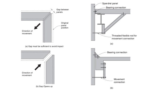
Figure 11.10 Provision for horizontal movement at panel corner junctions & Figure 11.12 Spandrel panel bearing and movement connections in steel and concrete. From SDA Pg. 178.
Windows & Curtain Walls
Earthquake-induced interstorey drifts pose a significant risk to glass in buildings, as evidenced by costly damages in past earthquakes. High-rise buildings, however, have shown less vulnerability to glazing damage. Protecting glass is crucial both for preventing injuries and minimizing economic losses. A simple but effective measure is to allow a small clearance around all sides of a glass pane to protect it from minor deformations during interstorey drift. For larger drifts, seismic mullions, which provide greater movement accommodation, are used. In terms of glass protection practices, there are variations depending on the country and building size. In New Zealand, for example, residential buildings often have minimal movement provision between glass panes and frames, while larger buildings adhere to stricter code requirements. These codes mandate that during significant earthquakes, glass panels must not fall out, even when interstorey drifts can reach up to 90mm in very flexible buildings.
Addressing large movements, especially at corners where two-dimensional movements occur, presents practical and visual challenges. Curtain walls, consisting of glass, plastic, or metal panels within a light frame, typically move easily with the structural frame, offering little resistance (Figure below). Incorporating seismic mullions into curtain wall systems may be necessary depending on the extent of interstorey drift. Achieving the necessary separation between glass panes and frames, though theoretically simple, demands high-quality workmanship to ensure unimpeded movement.
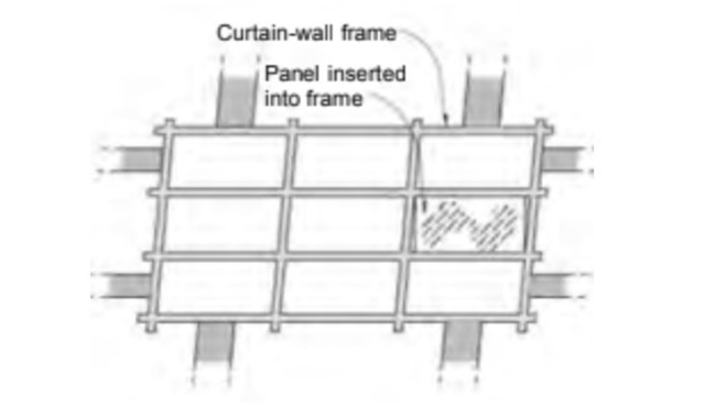
Figure 11.17 Elements of curtain wall. From SDA Pg. 181.
Suspended Ceiling
Bracing suspended ceilings significantly reduces operational disruptions in buildings during earthquakes. A typical suspended ceiling, hanging from wires, consists of a lightweight metal grillage supporting ceiling tiles. Unbraced, these ceilings sway like pendulums in an earthquake, causing damage to structures and other elements like fire sprinkler heads, leading to water deluges. Ceiling tiles can dislodge and fall, injuring occupants and damaging interiors.
To prevent such uncontrolled movement, suspended ceilings, including integrated light fixtures, require bracing (Figure below). The choice of bracing technique depends on the suspended ceiling manufacturers’ technical data, full-scale testing, and calculations. One effective method involves bracing the ceiling to the floor soffit or roof structure above. The seismic integrity of suspended ceilings also depends on the in-plane diaphragm action provided by the individual ceiling tiles, which can be compromised if small clips designed to prevent tile uplift are omitted. These principles hold true regardless of whether the ceiling is made of wood and plasterboard or is a modular system. Additionally, raised floors in some office buildings, which provide space and access to building services, require seismic restraint. This is typically achieved through perimeter restraint or cantilever action of vertical supports to resist horizontal accelerations.
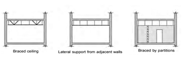
Figure 11.22 Bracing. From SDA Pg. 183.
Referenced from:
Seismic Design for Architects (SDA)
By Andrew Charleson
Published in 2008
Discussed in:
ARCH 332 Chapter 1 (RC Stairs)