While seismic damage typically highlights vertical elements, the importance of horizontal structures for seismic resistance is often overlooked. Crucial for force transmission, they intertwine with floor systems. Despite their invisibility in architectural plans, they significantly impact design decisions, relying on inherent strength and often sacrificially protected by damage to vertical elements, which can compromise building integrity. While diaphragms (structural slabs) constitute the predominant horizontal seismic force-resisting structural element, the structural necessity of collectors, ties, and bond beams is of crucial importance for earthquake resistance.
Diaphragms
The diaphragm configuration is the shape and arrangement of horizontal resistance elements that transfer forces between vertical resistance elements. Diaphragm penetration and geometrical irregularities are analogous to such irregularities in other building elements, leading to torsion and stress concentration, as in the figure below.
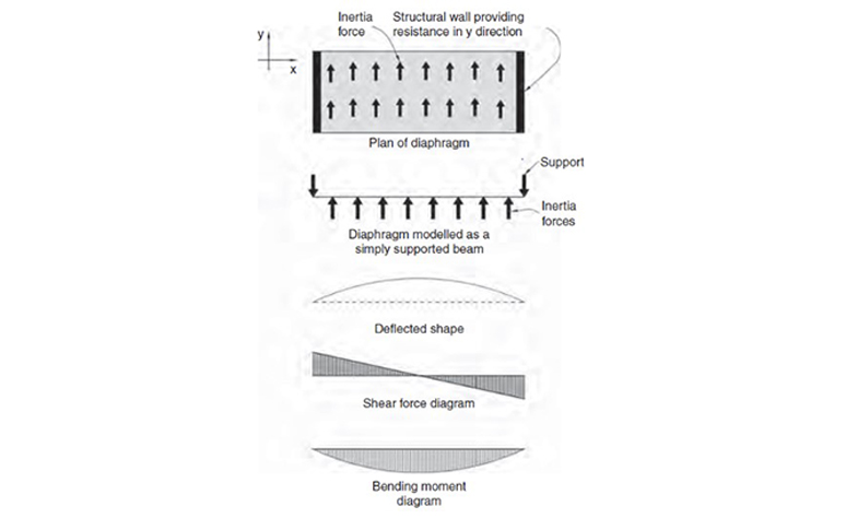
Figure 4.3 A diaphragm as a simple beam. From SDA Pg. 51.
When functioning as a diaphragm, a floor slab acts like a beam, albeit resisting horizontal rather than vertical forces and possessing a span-to-depth ratio much smaller than that of a typical beam. A diaphragm is, therefore, a beam that acts horizontally. As such, it requires stiffness and strength. Its often squat geometry avoids excessive horizontal deflections. However, a structural engineer needs to check that a diaphragm slender in plan is not too flexible.
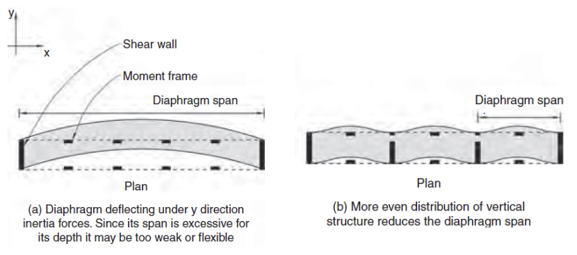
Figure 6.10 Degree of diaphragm deflection under seismic stress. From SDA Pg. 99.
Diaphragms are generally floors or roofs and so have major architectural functions aside from their seismic role. The shape of the diaphragm is dependent on the overall plan of the building and how it can be subdivided by walls or collectors. Architectural requirements such as staircases, elevators and duct shafts, skylights, and atria result in a variety of diaphragm penetrations. The general approach to the design of penetrations in diaphragms is to:
● Ensure that penetrations do not interfere with diaphragm attachment to walls or frames.
● Ensure that multiple penetrations are spaced sufficiently far from one another to allow reinforcing elements to develop their required capacity.
Bond Beam
Bond beams are horizontal structural components typically located at the eaves level of a building. In seismic design, bond beams play a crucial role in enhancing structural integrity. They serve to resist and transfer various forces generated by the roof and walls. In the absence of a ceiling diaphragm, which could provide horizontal support, the bond beam functions as a continuous horizontal beam. It plays an important role in transmitting roof and wall inertia forces to shear walls. Their strength in bending and shear allows them to transfer these forces down to the foundations.
Typically utilized in masonry construction, this principle is applicable across various construction types and materials. The figure below illustrates the use of bond beams spanning horizontally between lines of vertical bracing elements, such as shear walls.
When distances between bracing walls necessitate a wider or deeper horizontal beam, opting for a truss may be more suitable. Should bond beams be chosen, the wall thickness must be adequate to vertically span between the roof-level bond beam and the foundations.
The unique aspect of bond beams lies in their horizontal orientation, spanning between two parallel walls. This design allows bond beams to resist half of the out-of-plane forces on a wall and effectively transfer them to adjacent walls, aligning with the seismic force direction. It’s akin to taking a conventionally oriented beam and rotating it 90 degrees to operate horizontally. This thoughtful utilization of bond beams contributes significantly to the structural resilience of a building during seismic events.
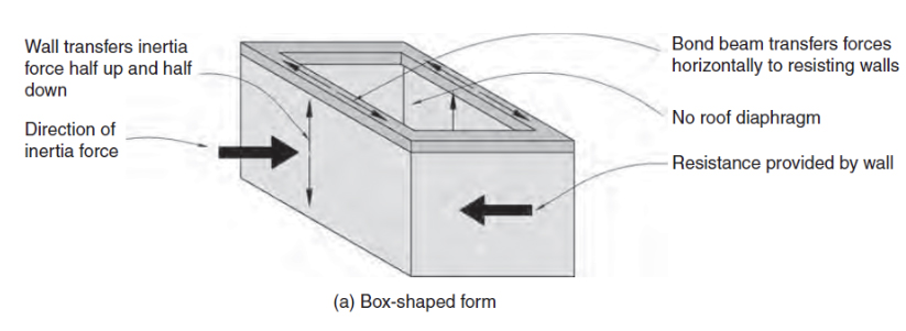
Figure 4.17 Typical bond beam framing on box-shaped design. From SDA Pg. 60.
Referenced from:
Seismic Design for Architects (SDA)
By Andrew Charleson
Published in 2008
Discussed in:
ARCH 332 Chapter 1 (Types of Slabs)
ARCH 332 Chapter 1 (RC Beams)
ARCH 332 Chapter 4 (RC Beam Design against Shear Failure)