General Concepts for Seismic Resistance
In simple terms, an earthquake is the back-and-forth ground movement during a seismic event. The time taken for one complete oscillation is the period of the earthquake, which dampens after the first movement. This oscillation causes the super-structure (building) to accelerate one way, followed by a back push, producing a vibration, as shown in figure below. The natural period of a building refers to the amount of time it takes for the building to vibrate at its natural frequency when subjected to an external force, such as an earthquake. This period dampens after the first impulse (as indicated in graph below) and varies significantly from building to building.
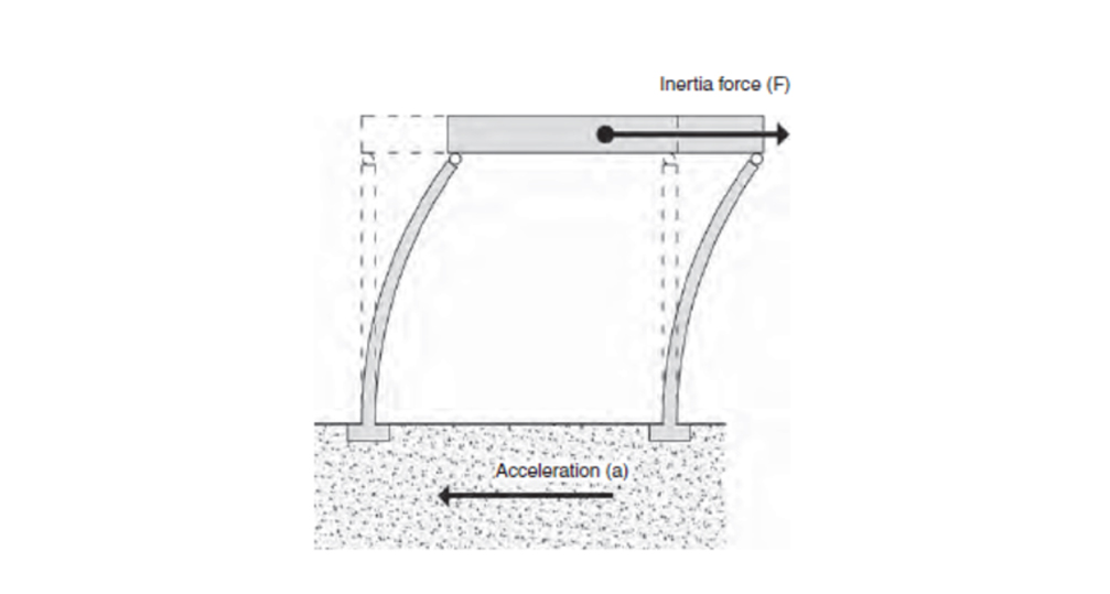
Figure 2.1 Ground oscillation causing building vibration. From SDA Pg. 16.
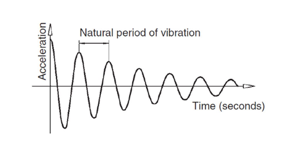
Figure 2.5(b) Record of building acceleration after impulse. From SDA Pg. 19.
In general, if the period of the earthquake is close to the natural period of a building, the building will experience more significant damage. This is known as resonance. Engineers design buildings to have natural periods different from the expected period of earthquakes in the area to minimize the potential for damage. However, some crucial factors, such as building height, weight, and structural system, can elongate or shorten a building’s natural period of vibration and the overall impact of the seismic event.
Building Weight
The primary factor influencing the force within a building is its weight, following Newton’s Law; the higher the mass, the higher the force of inertia. To reduce seismic vulnerability in quake-prone areas, it’s advisable to construct lighter buildings whenever feasible, even though prevalent construction materials tend to be heavier, like brick, stone, adobe, and reinforced concrete. Building ligh is the key to avoiding heavy damage in case of a seismic event. This principle applies to new constructions and renovations, allowing opportunities to decrease building weight by replacing heavy interior walls with lighter timber or steel frames. As shown in graph below the maximum response (movement) to a ground motion peaks at the resonance point and dampens afterward. Building weight can play an important role i tn determining the response conditions.
Building Height
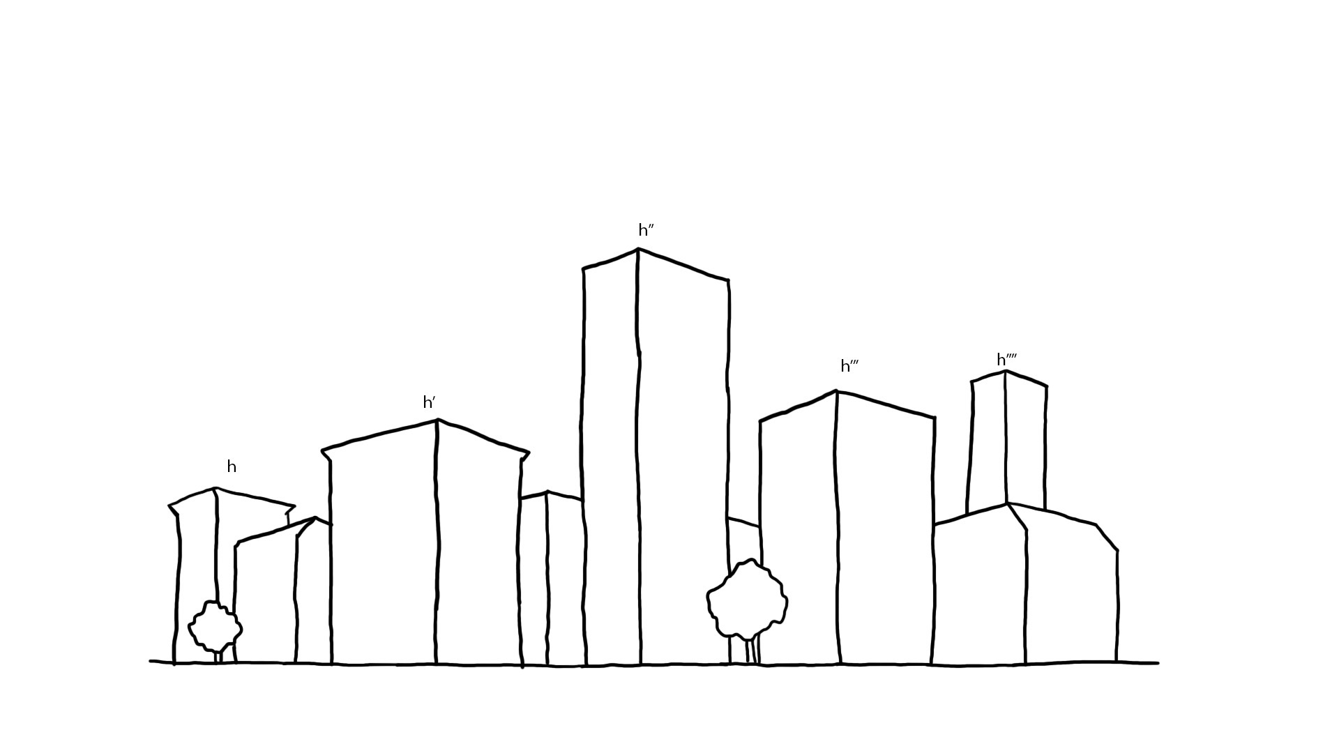
Depending on the height of the building, there might be other corresponding second, third, and higher periods of vibration, as shown in figure below. Particularly in low- to medium-rise buildings, most of the dynamic energy transmitted into them resonates with the first mode and its natural period of vibration and, to a far lesser extent, the second and higher modes. Because in the first mode, every part of a building moves in the same direction simultaneously resulting in the greatest overall inertia force, it is the most important.
As the building height increases while keeping the weight constant, the natural period of vibration increases. This reduces the acceleration response of the building and the consequent design inertia force. However, taller buildings, due to higher periods of vibration, have to be designed with flexible, lighter structures to sustain the oscillations (See Figure below).
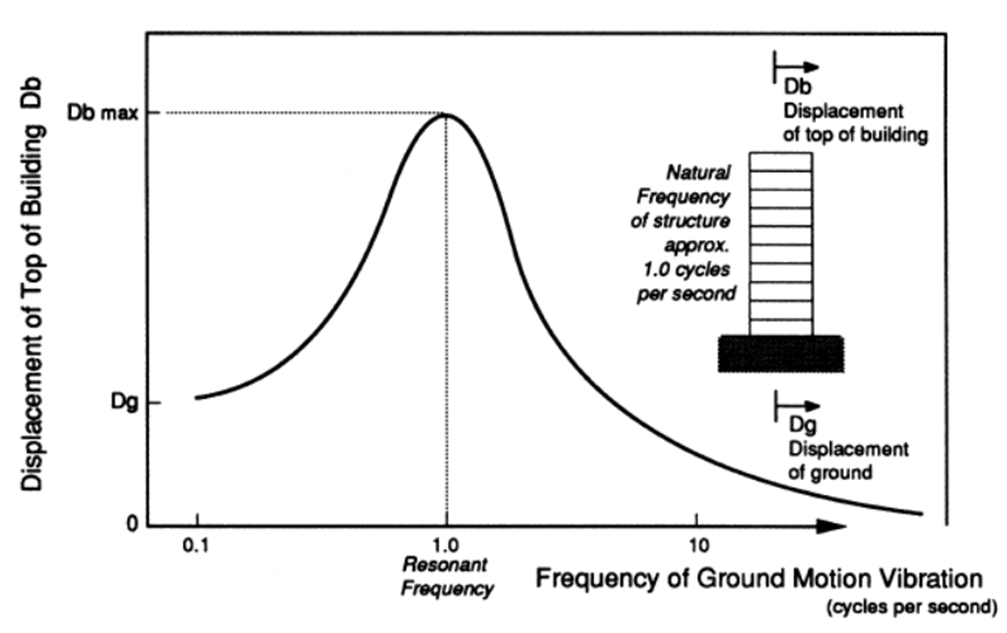
Figure 8.2 Diagram of maximum response to a building to ground motion. From EP Pg. 270.
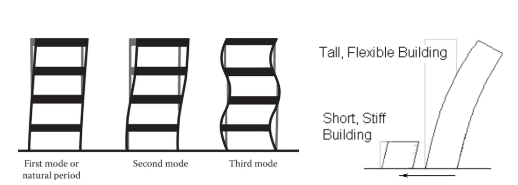
Tall building higher periods of oscillation & Flexibility in tall buildings
Damping
Damping absorbs earthquake energy and reduces resonance or the build-up of earthquake inertia forces, so it is very beneficial The response spectrum shows the effect of a particular earthquake ground motion on a range of buildings. The response spectrum for a particular ground motion shows what the maximum response would be to that ground motion for buildings of different natural frequencies. Damping, mainly caused by internal friction within building elements, causes the amplitude of vibrations to decay.
Reinforced concrete structures possess more damping than steel structures but less than those constructed of wood. However, the choice of structural materials is rarely, if ever, made on the basis of their damping values.
Its shape depends on the frequency content of the earthquake and on the degree of damping of the building. The graph below shows some typical examples of response spectra. Example A, near the epicenter on firm ground, peaks around 3 cycles/sec, posing a higher risk to low-rise structures. Example B, on soft soil and at a distance, peaks near 1.0 cycles/sec, posing greater danger to taller buildings while impacting low-rise ones less.
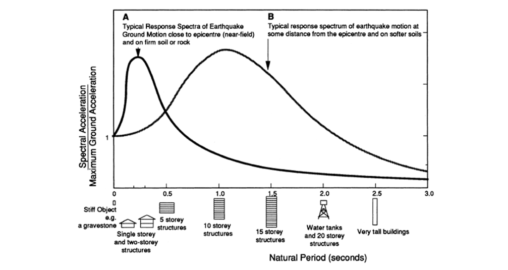
Figure 8.3. Diagram of maximum response and frequency dampening of building ground motion. From EP Pg. 271.
Ductility
Ductility can be simply described as The ability of some structural systems to experience extensive deformation and damage without loss of load-carrying capability. Ductility has a large influence on the magnitude of accelerations and seismic forces a building is designed for, just like its natural period of vibration. Steel is an inherently ductile material and is thus very suitable for building in earthquake areas. Concrete and all types of masonry, without reinforcement, are brittle materials, but by means of embedment of steel reinforcement, suitably placed, they can be made to perform in a semi-ductile manner, making them suitable for earthquake-resistant construction. A ductile material, on the other hand, like steel, reaches its elastic limit and then deforms plastically without breaking unless elongated beyond the limit. Ductile structural materials don’t necessarily guarantee ductile structures. The critical cross-sections of members and their connections need to be properly proportioned and detailed to completely exploit the ductile nature of the material. Figure below indicates a typical diagram of a ductile structure with a flexible allowance of structural response to the ground motion.
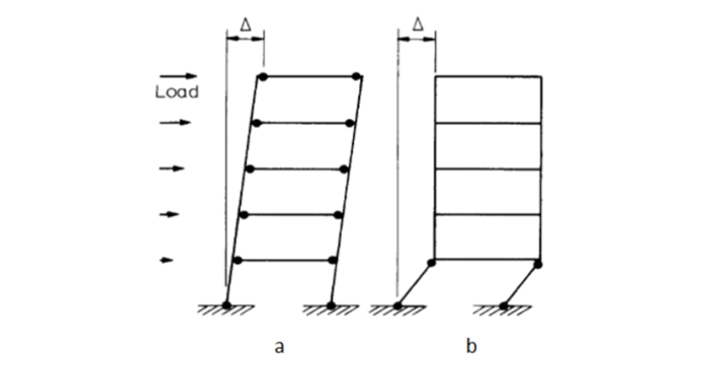
Typical swaying response of ductile structure.
Strength
The superstructure of every building requires sufficient structural strength to resist the bending moments and shear forces 2 caused by seismic forces and a foundation system capable of preventing overturning and sliding.
Consider the building shown in the figure below Two shear walls resist inertia forces in both the x and y directions and transfer them to the foundations. The walls are subject to bending moments and shear forces for which they must be designed in order to satisfy the requirements of the seismic design code. Bending and shear actions, which increase from the roof level to reach their maximum values at the bases of the walls, are resisted by the foundations and transferred into the ground.
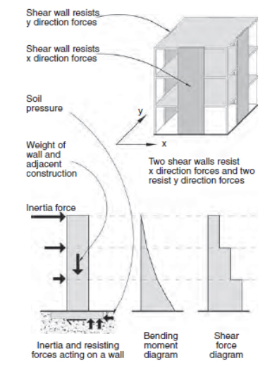
Figure 2.12 A building with shear walls resisting inertia forces. From SDA Pg. 25.
Stiffness
Stiffness in built structures is defined as a quantitative measure of the amount of force required to produce a unit amount of deflection or displacement in a structure. The stiffer a structure, the less it deflects under seismic force although, as noted previously, a smaller natural period of vibration caused by a stiffer structure will usually result in a structure attracting greater seismic force. Even though a building might be strong enough, if its stiffness is so low that it deflects excessively, its non-structural elements will still suffer damage, and it will become prone to toppling. For these reasons, design codes limit the maximum seismic deflections of buildings. In framed buildings, additional important rules of design must be observed. One requirement is that columns should be stiffer than the beams that frame them. If this is the case, the beams will fail before the columns, limiting failure to the area supported by the beam and enabling the beams to be used as energy absorbers; where the columns begin to fail first, failure tends to occur very rapidly under their vertical load. Central cores, Shear Walls, and diagonal bracing, as shown in the figure below are all methods to increase structural stiffness.
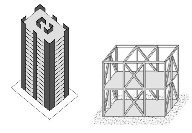
Figure 5.2 Strategies to increase building stiffness to inertia forces. From SDA Pg. 64.
Torsion
Torsion occurs with twisting about a vertical axis for structures or a longitudinal axis for individual structural elements. Building torsion (see fig. below) occurs either where structural elements are not positioned symmetrically in plan or where the center of rigidity (CoR) does not coincide with the center of mass (CoM).
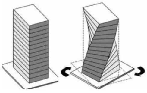
Seismic vibrations in the building.
Assume the single-storey building in figure below with four identical square cantilever columns (1m x 1m) resist uniform inertia forces. Each column, due to equal stiffness, bears 25% of the total force, ensuring equilibrium in both y direction and rotation. The line of force through the CoM, therefore, coincides with the line of resistance through the CoR. The building is subsequently in both y direction and rotational equilibrium.
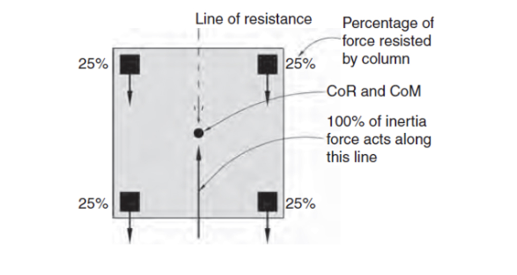
Figure 2.16 Identical columns CoR in line with CoM. From SDA Pg. 28
In the figure below(left), deeper right-hand columns (2m) shift the CoR significantly rightward due to increased stiffness. The larger columns now bear 89% of the force, and the left-hand columns 11%. The CoR position shifts to 1/9th the distance between column centrelines from the right columns’ centreline, causing an offset, generating torsional moments and a clockwise building plan twisting around the CoR. Further increases in right column depths (Figure below (right)) move the CoR closer to their centreline, amplifying the eccentricity nearly to half the building width.
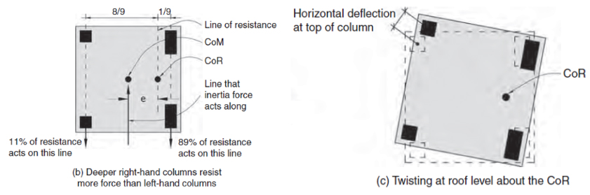
Figure 2.16 Identical columns CoR in line with CoM. From SDA Pg. 28
Key Principles for Vibration Reduction
Structural elements must fulfill two functions: first, to resist forces, and second, to transfer these forces to other members and eventually into the ground. The adequacy of a force path is verified by following it step-by-step, element by element. Three questions are addressed and answered at each step – what resists the force, how, and where is it transferred to? Following are a few key structural considerations for reducing the impact of inertia forces on a building however, aseismic design is not restricted to these considerations.
● The load-bearing members are uniformly distributed.
● The columns and walls are continuous and without offsets from the roof to the foundation.
● All beams are free from offsets.
● Columns and beams are co-axial;
● Reinforced concrete columns and beams are nearly the same width;
● No principal members change sections suddenly;
● The structure is as continuous (redundant) and monolithic as possible.
Design Configuration for Aseismic Design
Seismic-resistant design is intended to achieve two objectives:
● Protect human lives.
● Limit building damage.
The former is achieved by ensuring strength and ductility to prevent partial or total collapse during rare strong earthquakes. The latter focuses on minimizing damage in more frequent, lesser earthquakes to reduce economic losses and maintain building functionality. Figure below highlights four potential types of failures of a reinforced column in response to ground motion and inertia forces. This is why strength enhancement and damage imitability are at the core of capacity design for seismic resistance. Capacity Design approach involves the following three steps:
● Select a deflection pattern, allowing the structure to absorb ample earthquake energy before reaching its deflection limit.
● Establish a strength hierarchy to enable plastic action in non-critical members, preventing brittle failure and preserving structural integrity.
● Detail structural areas that are intended to act as fuses so they avoid severe damage and excessive loss of stiffness and strength.
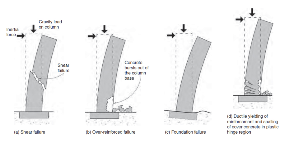
3.1.2 Typical four causes of RCC column failure to considered while capacity designing of aseismic structure. From SDA Pg. 44.
Referenced from:
Seismic Design for Architects (SDA)
By Andrew Charleson
Published in 2008
Earthquake Protection (EP)
By Andrew Coburn & Robin Spence
Published in 2002
Discussed in:
ARCH 332 Chapter 7 (Major Shortcomings)
ARCH 252 Week 3 Lecture (Loads)
ARCH 332 Chapter 7 (Issues of Stiffness)
ARCH 231 Lecture 1 (Types of Stress)
ARCH 252 Week 4 Lecture (Structural Safety and Regulations)
ARCH 332 Chapter 1 (R.C Structural Members)