Soft and Weak Stories
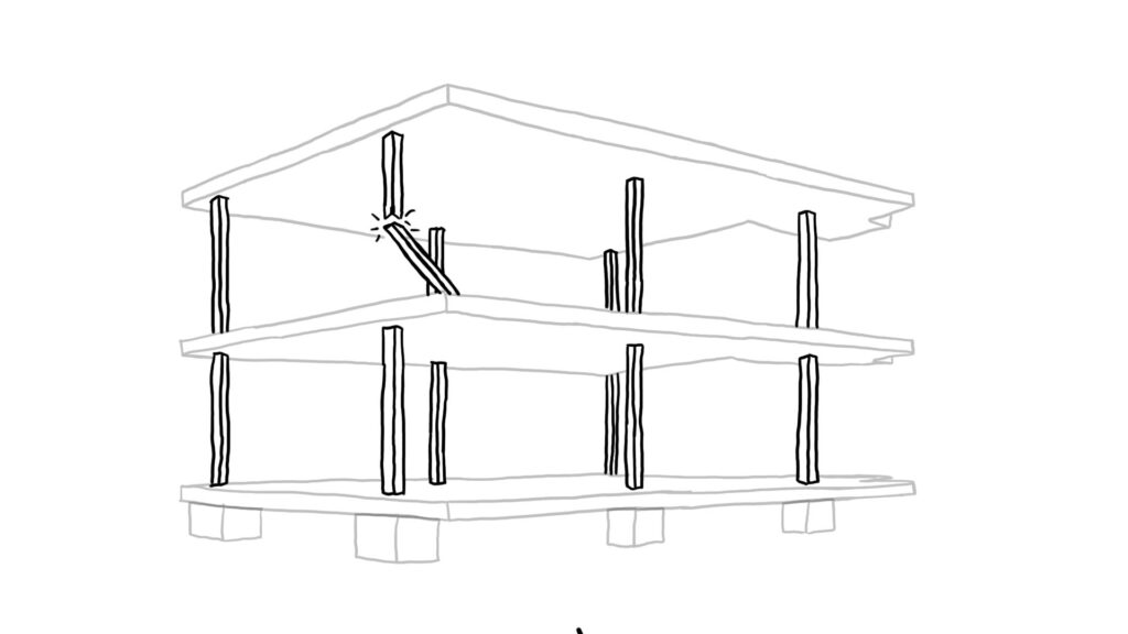
A soft story exhibits a significant decrease in lateral stiffness from the level immediately above it, while a weak story experiences a notable reduction in strength compared to the story above. The key attributes of a weak or soft first story involve a discontinuity in strength or stiffness, particularly at the second-story connections. This disparity arises because the diminished strength or increased flexibility in the first-story structure leads to extreme deflections, concentrating forces at the second-story connections.
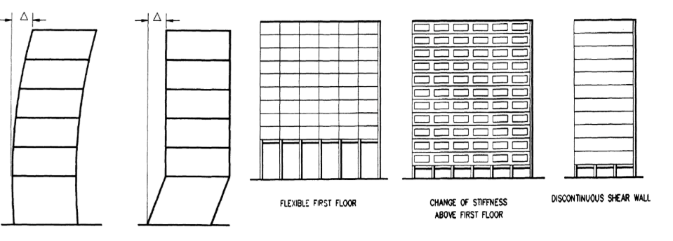
In cases where all stories possess similar strength and stiffness, earthquake-induced deflection is evenly distributed. However, if the first story is considerably weaker or more flexible, a substantial portion of the building deflection concentrates there, with resultant forces at the second-story connections (see Figure 1). The soft-story issue may stem from four fundamental conditions, illustrated in Figure 1a.
To address a desire for a heightened first story:
• Introduce bracing to enhance column stiffness up to a level comparable to the superstructure.
• Add columns at the first story for increased stiffness.
• Modify the design of the first-story columns to increase stiffness.
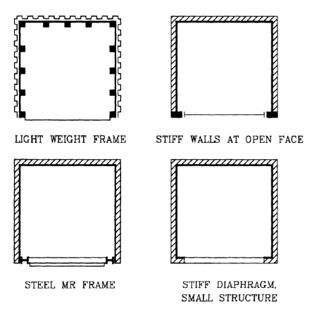
When a large opaque wall is necessary in a location prone to creating a soft first story:
• Ensure the wall is not part of the lateral load-resisting system.
• Decrease the wall mass using lightweight materials and hollow construction.
• If a heavy wall is essential, ensure it is detached to allow the superstructure to deflect comparably to the first floor.
Columns
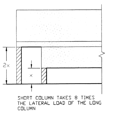
Seismic forces distribute proportionally to the stiffness of resisting members. Consequently, variations in the stiffness of supporting columns or walls result in a gravitational pull of forces towards the stiffer, usually shorter elements, as depicted in Figure 2. Notably, stiffness (and, consequently, forces) fluctuates approximately in relation to the cube of the column length.
A uniform configuration of short columns supporting a floor amplifies the forces acting on that floor, heightening the risk of failure. This scenario often includes deep and stiff spandrel beams, rendering the columns notably weaker than the beams.
Furthermore, mixing of columns with differing stiffness on different facades may induce torsional effects. In this context, the building adopts characteristics similar to the discussed varying perimeter resistance, amplifying the potential for torsional stress.
Vertical Setbacks
A vertical setback refers to a horizontal or nearly horizontal displacement within the plane of an exterior structure facade. The challenge with this form stems from discontinuity, specifically the sudden shift in strength and stiffness, often concentrated at the setback line or “notch.”
The impact of the setback is contingent upon the relative proportions and absolute sizes of distinct building components. Additionally, the symmetry or asymmetry in the tower and base’s plan influences force dynamics. When either or both exhibit dynamic asymmetry, torsional forces are introduced, resulting in intricate structural analysis and behavior.
Visualizing the setback configuration as a vertical reentrant corner, stress paths are diverted around corners due to the notches, creating a less direct route. Consequently, minimizing the size of setbacks or notches mitigates potential issues.
In a broader context, addressing the setback problem mirrors solutions for its horizontal counterpart, the reentrant corner plan. One approach involves seismic separation in plan, allowing segments of the building to react independently, offering a conceptual resolution to the setback challenge.
Variations in Perimeter Strength and Stiffness
Arranging resistance perimeter elements for balanced resistance is crucial for minimizing torsional effects. The long lever arm, in relation to the center of rigidity, enhances effectiveness. Extreme detrimental effects can result if resistance is unbalanced.
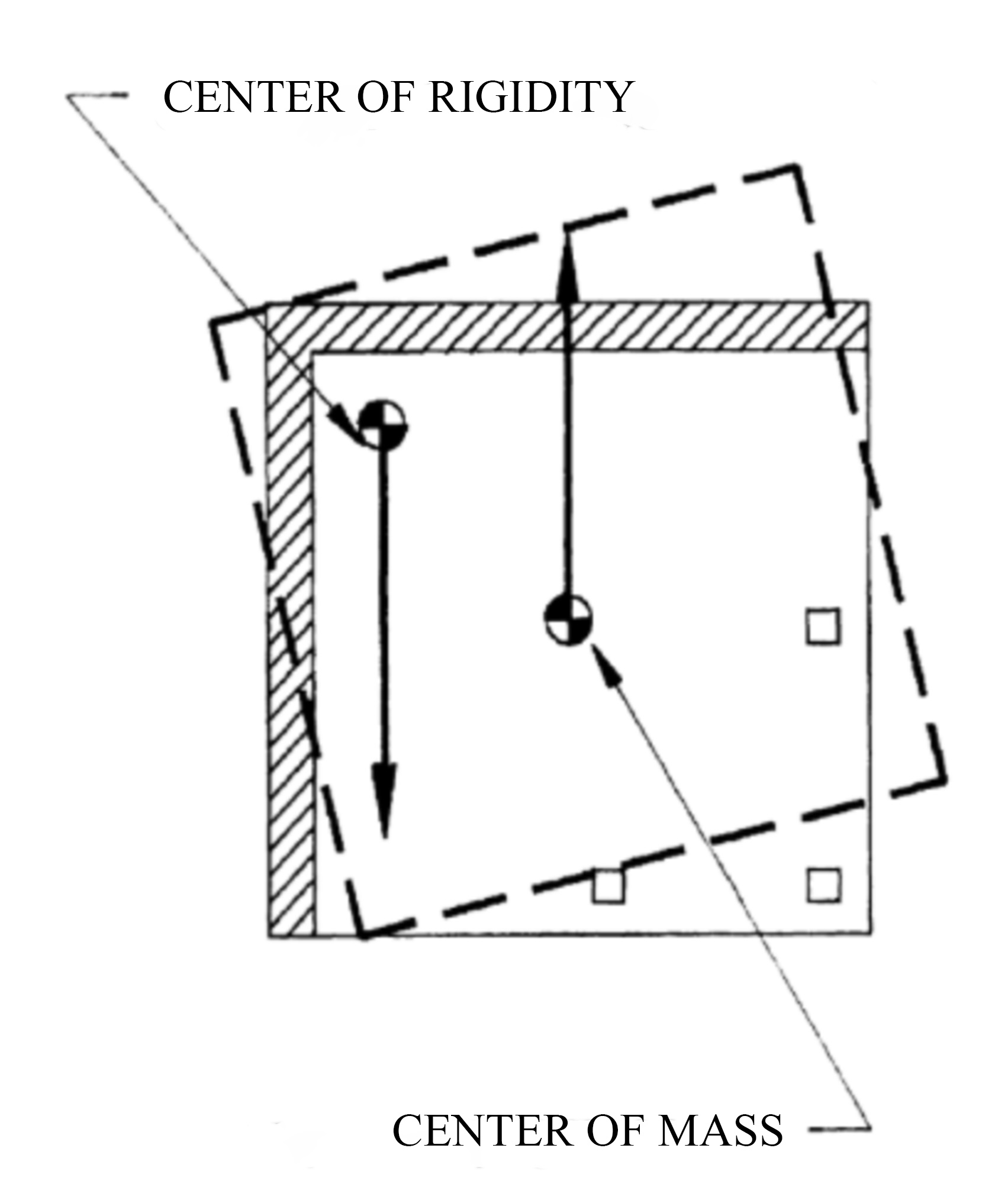
This issue is prevalent in geometrically symmetrical yet structurally irregular buildings, especially for seismic design. When strength and stiffness vary widely around the perimeter, the centers of mass and resistance do not align. Consequently, torsional forces may induce rotation around the center of rigidity, as depicted in Figure 3.
Addressing this challenge involves minimizing torsion risk and achieving resistance balance along the perimeter. Figure 4 illustrates four alternative strategies to attain this objective. The emphasis lies in configurations that mitigate torsional effects by strategically distributing resistance, aligning with the overall goal of enhancing structural stability.
Nonparallel Systems
Nonparallel load-resisting elements pose a heightened risk of torsional forces during ground motion due to the inability of the centers of mass and resistance to align across all directions. Additionally, the narrower segments of a structure often exhibit greater flexibility compared to wider portions, further accentuating the susceptibility to torsion.
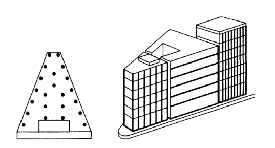
Complicating matters, irregularities in strength and stiffness within perimeters, as illustrated in Figure 5, contribute to the issue. Particularly noteworthy is the triangular or wedge-shaped configuration arising from acute-angle street intersections. These structures typically incorporate a robust, rigid party wall juxtaposed with more pliant sections facing the street, culminating in a design highly predisposed to torsional forces.
Addressing this challenge may involve implementing specialized design solutions to enhance torsional resistance in the narrower segments. However, achieving this objective while preserving open facades or internal spaces poses a considerable design challenge. Balancing structural integrity with aesthetic considerations becomes a critical aspect of navigating the complexities associated with mitigating torsional vulnerabilities.
Components and Connection
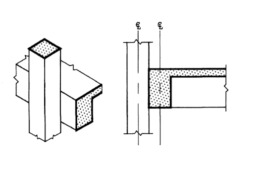
This issue mirrors typical challenges in overall building configuration but at a micro level. Architectural detailing can impose dimensional or location constraints on structural design, potentially leading to force irregularities, stress concentration, or local torsion. The crux of the matter lies in beam-column connections, crucial for structural integrity and aesthetics but prone to high stress.
Ideally, structural detailing should facilitate direct load transfer, minimizing local eccentricity and concentrating forces at a specific point. However, architectural detailing may yield inadequate sizes and eccentric or disjointed load paths (see Figure 6), a critical concern for reinforced concrete structures where spatial constraints hinder proper reinforcing placement.
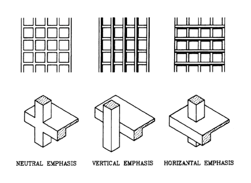
Detailed design is an important element in architectural expression. For instance, the design of the perimeter beam-column connection can impart a predominantly horizontal, vertical, or neutral emphasis to the building (see Figure 7). Yet, the structural ramifications of these variations may elude the architect.
Effective collaboration between the architect and engineer is imperative to prevent architectural detailing from imposing unfavorable structural constraints, ensuring a harmonious balance between aesthetics and structural integrity.
Foundation Failures
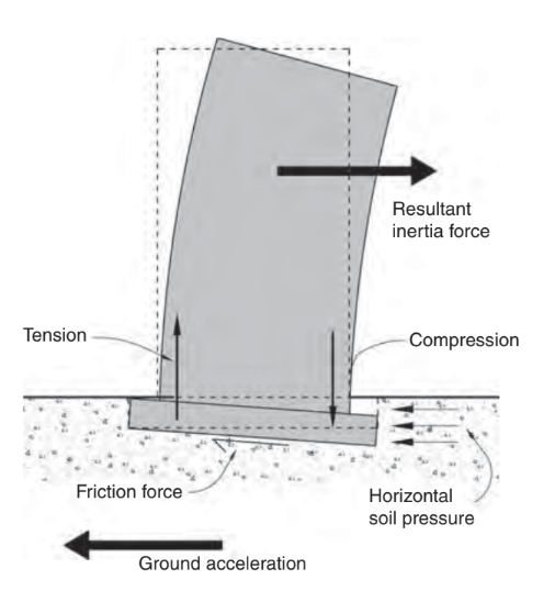
The generation of inertia-induced overturning moments results in heightened compression and potentially tension forces within the end columns of a moment or braced frame, as well as in the chords of a shear wall (see Fig. 8). Foundation failure may occur if the foundations are inadequately designed to withstand these forces.
Some buildings have the potential to withstand earthquakes by adopting a rocking motion. When a building initiates rocking, its natural vibration period increases, consequently reducing its acceleration response. This phenomenon, particularly applicable to shear wall buildings requiring seismic retrofitting, may justify less intrusive strengthening efforts.
Engineers employ a proactive approach to prevent foundation failure by carefully evaluating the design forces and appropriately sizing the foundations. The most secure foundation design method involves the application of the Capacity Design approach. Foundation failure is averted when the foundations are designed to be stronger than the structural fuses present in the superstructure members.
Referenced from:
Architectural Considerations (AC)
By Christopher Arnold
Published in 2001
Seismic Design for Architects (SDA)
By Andrew Charleson
Published in 2008
Urban Design in Seismic-Prone Regions (UDSPR)
By Hoosein Bahrainy & Ameneh Bakhtiar
Published in 2022
Discussed in:
ARCH 331 (Damage Inducing Architectural Features)
ARCH 332 Chapter 7 (Weak/Soft Stories)
ARCH 332 Chapter 1 & 5 (Reinforced Concrete Columns)
ARCH 332 Chapter 7 (Diff. in Stiffness & Center of Gravity)
ARCH 252 Week 6 Lecture