These issues pertain to the overall building configuration and are applicable across all configurations. In accordance with current seismic codes, irregularities encompass a range of configuration variables that notably impact the building’s seismic performance. While definitions may differ, consensus exists on the key configuration irregularities deemed significant.
Building Size
The impact of configuration irregularities varies between small wood frame houses and larger buildings. In a compact wood frame structure, potential problems, while serious, can be mitigated economically and unobtrusively. This is attributed to the structure’s lightweight nature, resulting in low inertial forces. Additionally, short spans and a higher prevalence of walls allow for effective load distribution.
Conversely, larger buildings face escalating costs when deviating from fundamental layout and proportion principles. As forces intensify, reliable performance diminishes compared to a better-configured equivalent building. The magnitude of a structure inversely affects the flexibility in arranging its components. While a 300-foot bridge span offers options like beams, arches, trusses, or suspension systems, a 3000-foot span mandates a singular suspension structure. With increasing size, structural design becomes more stringent, emphasizing the need for meticulous discipline.
Building Proportion
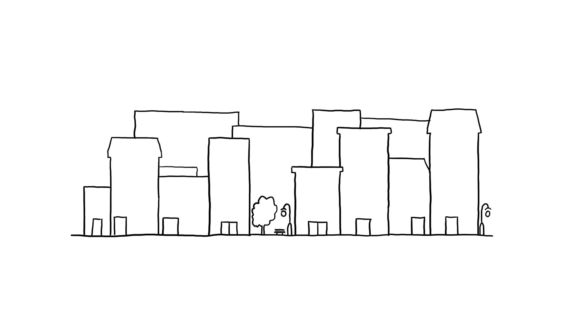
In seismic design, the significance of a building extends beyond its absolute size to include proportions. Particularly for tall structures, the slenderness ratio (height/least depth), calculated in the same way as for an individual member, takes precedence over height. The focus shifts from height alone to the critical consideration of this ratio. In response to the escalating cost of urban land, a prevalent trend emerges: the design of exceptionally slender “sliver” buildings. While these structures may not boast extraordinary height, their noteworthy feature lies in a substantial height/depth ratio. This approach optimizes land use and addresses economic constraints, reflecting an evolving paradigm in architectural design.
Building Symmetry
Symmetry, a key geometric attribute in building plan configuration, refers to the alignment of the center of mass and the center of rigidity. It is widely advocated in codes and textbooks due to its role in preventing torsion and stress concentrations arising from eccentricity between these centers. However, while symmetry is favored, reentrant corners in a building do not necessarily imply asymmetry; instead, they denote irregularity as defined in seismic codes.
Merely achieving symmetry is not adequate; its benefits become evident only when coupled with simplicity. The impact of symmetry extends beyond overall shape to influence design and construction details. Examining past earthquake events reveals that even minor deviations in symmetry can significantly affect a building’s performance, especially concerning shear-wall design and the use of service cores as major lateral-resistant elements.
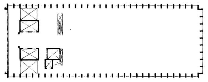
Notably, a building may appear geometrically symmetrical externally but harbor asymmetry in its structural system arrangement, termed “false symmetry.” Interior structural cores, unsymmetrically arranged for planning reasons, can lead to undesirable torsional responses (See Fig.1 below).
Architectural constraints may render symmetrical design impractical, necessitating the subdivision of the building into simpler elements. While tall structures tend toward symmetry and simplicity, seismic challenges are most pronounced in low to medium-height buildings, where ample choices exist regarding plan form and mass disposition.
Plan Density and Perimeter Resistance
Earthquake forces exert the greatest impact at a building’s base. The lowest story must not only bear its own lateral load but also withstand the shear forces from all the stories above, mirroring the accumulation of vertical gravity loads. This challenge is compounded by programmatic and aesthetic criteria, often mandating the removal of substantial material at this level, contradicting the seismic ideal of maximizing vertical resistant elements at the base.
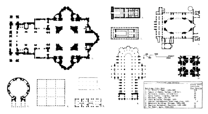
A noteworthy metric in this context is ground-level vertical plan density, calculated by dividing the total area of vertical structural elements by the gross floor area. Modern framed buildings exhibit a remarkable reduction in structural plan density compared to their historic counterparts.
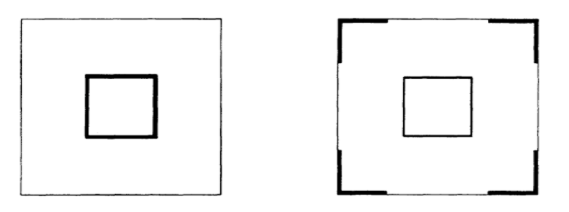
In figure 2 above, despite both configurations being symmetrical with equal shear wall amounts, the placement of walls differs significantly. Walls on the right create larger lever arms to resist overturning and torsional moments effectively. Optimal placement of resisting members along the perimeter, whether walls, frames, or braced frames, is consistently desirable for countering lateral forces, torsion, or both, enhancing seismic performance.
The detailing of connections is often cited as a key factor in seismic performance, since the more integrated and interconnected a structure is, the more load distribution possibilities there are.
Reentrant/Inside Corners
The common characteristic of overall building configurations, assuming L, T, H, +, or a combination of these shapes in plan, is the reentrant or “inside” corner. These configurations pose two related issues. Firstly, they generate rigidity variations, leading to differential motions among different building parts and causing local stress concentration at the reentrant corner notch.
In figure 04, with north-south ground motion emphasis on the L-shaped building, the north-south wing tends to be stiffer than the east-west wing due to geometric reasons. Although these wings are interconnected, they attempt to move differentially at their notch during seismic events, creating a pulling and pushing effect (Figure 5). For ground motions along the other axis, the wings reverse roles, but the differential problem remains.
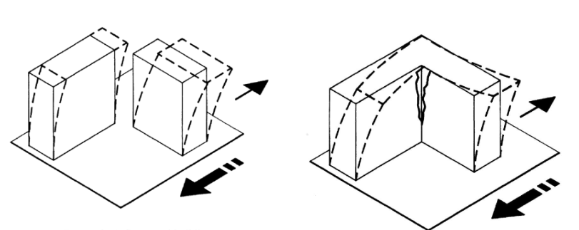
The second problem is torsion, arising from the inability of the center of mass and center of rigidity to geometrically coincide for all earthquake directions.
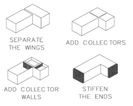
Torsional effects and stress concentration at the notch are interconnected, their severity is dependent on factors such as building mass, structural systems, wing length, aspect ratios, wing height, and height/depth ratios. Two alternative solutions emerge: structurally separating the building into simpler shapes or reinforcing strong ties at stress concentration lines while strategically placing resistance elements to mitigate torsion.
Referenced from:
Architectural Considerations (AC)
By Christopher Arnold
Published in 2001
Urban Design in Seismic-Prone Regions (UDSPR)
By Hoosein Bahrainy & Ameneh Bakhtiar
Published in 2022
Discussed in:
ARCH 231 (Force, Stress and Load)
ARCH 332 Chapter 7 (Plan Irregularity)