Horizontal members bear the responsibility of resisting inertia forces, channeling them into the vertical structure. The vertical elements, encompassing walls, columns, or diagonal braces, counteract these forces, transmitting them downward into the foundations. The seismic resistance required in the vertical structure differs markedly from that designed for gravity forces.
Gravity-resisting structures typically adopt post-and-beam or load-bearing wall construction (Figure below). In these systems, vertical elements support loads through compression, necessitating adequate cross-sectional dimensions to prevent buckling. However, gravity frameworks typically exhibit minimal resistance to horizontal forces.
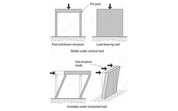
Figure 5.1 Instability of two gravity force resisting structures against
horizontal forces. From SDA Pg. 63.
Post-and-beam structures with pins at the top and bottom of columns are inherently unstable. Frames designed solely for gravity forces may gain stability against horizontal forces based on column slenderness. Load-bearing walls, while potentially offering bracing as shear walls, require intentional design and detailing to realize this capacity effectively. The choice of vertical structural systems to resist horizontal seismic forces is quite limited. The three most common systems illustrated in figure below comprise:
● Shear walls
● Braced frames, and
● Moment frames.
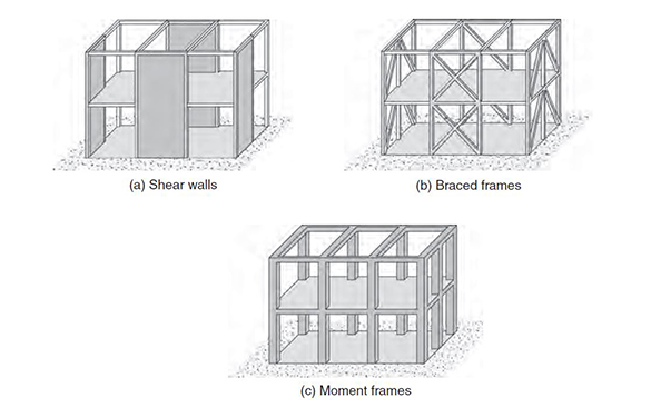
Figure 5.2 Typical Seismic Force Structure. From SDA Pg. 64.
Shear Walls
Reinforced concrete shear walls boast the most robust seismic resistance track record among various structural systems. Even buildings with walls not explicitly detailed for seismic performance but with well-distributed reinforcement have proven effective in preventing collapse during past earthquakes.
Shear walls counteract horizontal forces within their plane primarily through length and, to a lesser extent, thickness. Achieving strength and stiffness against horizontal forces typically necessitates a rigid connection to foundations. Like other seismic-resistant systems, shear walls should be continuous from foundation to roof, with the material possessing adequate strength to resist forces transferred by diaphragms.
As a general rule, shear walls are ideally positioned in the middle of each half of a structure, a critical consideration for both high-rise buildings and dwellings requiring shear walls. Following this, shear walls must be symmetrically constructed around the center axis of the structure. See figure below. Put differently, if a shear wall is on the north side, an excellent parallel shear wall is required on the south side. Similarly, on the opposite side of the central axis, a building necessitates a shear wall mirroring the one on the Northwest corner if there is a shear wall located at the Northeast corner of the structure.
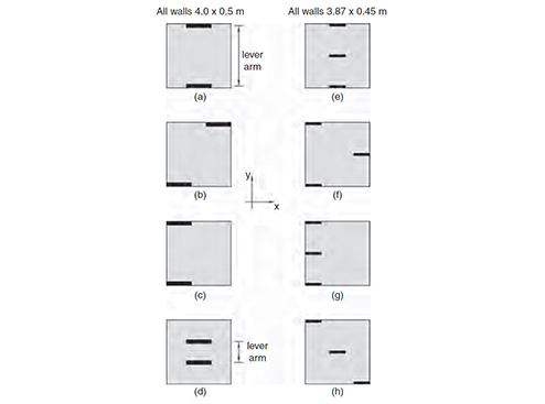
Figure 6.3 Ground floor plan showing different shear wall layouts for symmetrical resistance. From SDA Pg. 95.
- Braced Frames
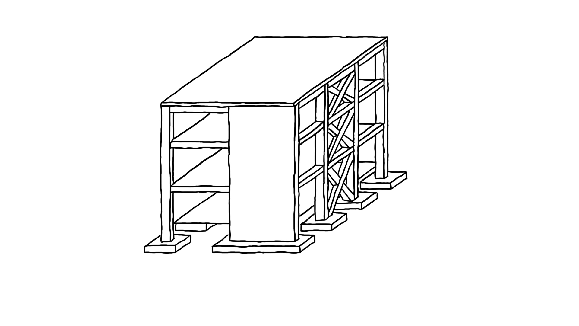
Braced frames exhibit diverse configurations, typically comprising posts, beams, and one or two diagonal bracing members per story that fully triangulate the structure—a vertical truss in essence. All joints in these frames can be pinned, and figure below illustrates six basic types.
With the exception of tension-only braced frames, diagonal members are designed for both tension and compression, necessitating sizable cross-sections to resist buckling. In multi-story steel construction, steel tubes or universal column sections are commonly used for compression-resistant bracing members.
Tension-only bracing finds particular utility in low-rise and light-industrial buildings due to its cost-effectiveness, leveraging steel’s optimal structural mode—tension. The slender nature of bracing members, such as steel rods or flats, minimizes compressive strengths. Eccentrically braced frames rank as the most ductile among all types. The intentional eccentricity in their connections deviates from the traditional concentric practice, leading to seismic bending moments and shear forces in the beam fuse region between braces. Similar to shear walls, braced frames demand robust foundations. Despite their lighter construction resulting in lower gravity forces compared to shear walls, additional foundation stability might be necessary.
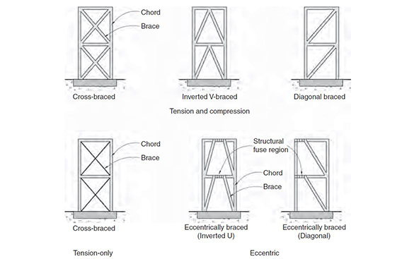
Figure 5.23 Common types of braced frames. Fgure sourced from SDA Pg. 77.
Moment Resisting Frames
A seismic moment frame necessitates three fundamental qualities to resist horizontal forces: deep columns capable of withstanding significant bending moments, beams and columns with comparable depths, and rigid connections between columns and beams. As the frame deflects sideways to counter seismic forces, beams and columns undergo substantial bending moments (figure below).
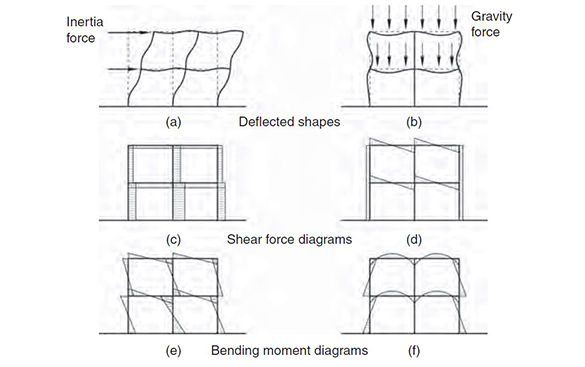
Figure 5.32 Comparison of Horizontal and vertical forces on moment frames from SDA Pg. 81.
Despite their open configuration aligning with contemporary preferences for spatial planning, minimal structural footprints, and enhanced natural light and views, moment frames have notable structural requirements.
The first prerequisite is relatively deep columns, measured in the frame’s acting direction, providing adequate stiffness, bending, and shear strength. For ductile strong column – weak beam frames, column depths usually equal or exceed beam depths. Reinforced concrete moment frames require special reinforcement detailing, necessitating column cross-sections larger than 230 mm wide by 400 mm deep, particularly for buildings exceeding one storey.
Moment frame beams, facilitating direct bending moment transfer, share approximately the same depth and width as the columns they frame. The beam depth exceeds that of a typical floor slab, seldom being less than span/12, while slab depths typically range from span/25 to span/30. Moment frame beams, unlike slabs, should ideally form continuous straight lines in the plan.
Seismic performance is optimal in frames with regular elevation and plan configurations, featuring approximately equal bay widths and correctly oriented columns. Multi-bay frames with identical beam spans exhibit superior seismic resistance, with an optimum distance between column centrelines ranging between 5 and 8 m. Beyond 8 m spans, deeper beams may necessitate increased inter-storey heights (figure below).
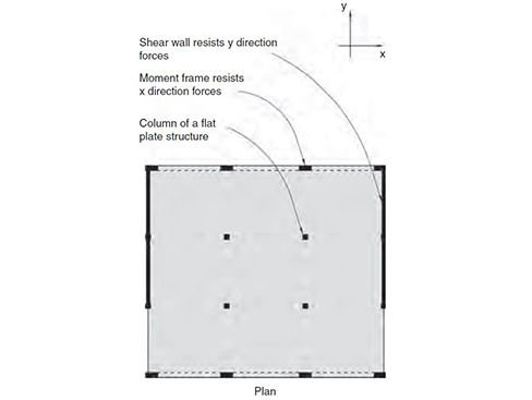
Figure 5.38 Plan of a flat plate gravity-resisting structure provided with seismic resistance by a pair of shear walls and moment frames. From SDA Pg. 84.
Referenced from:
Seismic Design for Architects (SDA)
By Andrew Charleson
Published in 2008
Discussed in:
Arch 332 Chapter 1 (RC Shear Walls)
Arch 332 Chapter 4 (Eccentricity in Column Design)